


MASS IS A NECESSARY INGREDIENT FOR LOW BASS
Generally all low frequency loudspeaker systems operate on a principle of mass. No practical sized loudspeaker driver is effective to very low frequencies without adequate mass and some form of external physical assistance. Typically a 15" loudspeaker will begin to unload or stop being effective when the frequency goes below 500Hz yet we see conventional subwoofers with drivers that size operating at frequencies down to 20 Hz and below.
Mass gives the above un-mounted driver the ability to continue to produce sound efficiently below 500Hz. Mass causes an increased acceleration as the frequency lowers resulting in continued velocity and output. Ideally a driver could produce low frequencies without the box if cancellation of front and rear waves didn't occur. A box or a baffle must be used to prevent this occurrence bringing a host of new compromises and considerations. The graph (fig. 1) below could be the output of a typical low frequency driver operating (without the box or cancellation conditions to affect its mass reactance) with mass allowing it to respond to lower frequencies. As the frequency goes lower the mass inertia causes the cone to travel further maintaining power response to a frequency lower than that determined by size alone.
Fig. 1 is the actual graph of a close microphone position (3") of a MAGELLAN VI su. ETL technology synthesizes mass as a coherent acoustical pressure and as a function of the frequency.
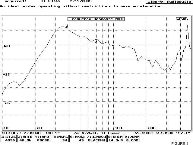 It
is a desirable to have this rise in output at the transducer (or
port) to compensate for lower transducer area available at low frequencies.
The 6db/oct slope effectively compensates for the smaller area driver
power response. The slope is the result of acoustic forces on the
diaphragm by reflex action and transmission line feedback. The roll
off function below the TL feedback synthesized peak at 35Hz is normally
characterized by an electronic filter however this function is an
acoustic one in ETL/Reflex Bass Extension Modules.
It
is a desirable to have this rise in output at the transducer (or
port) to compensate for lower transducer area available at low frequencies.
The 6db/oct slope effectively compensates for the smaller area driver
power response. The slope is the result of acoustic forces on the
diaphragm by reflex action and transmission line feedback. The roll
off function below the TL feedback synthesized peak at 35Hz is normally
characterized by an electronic filter however this function is an
acoustic one in ETL/Reflex Bass Extension Modules.
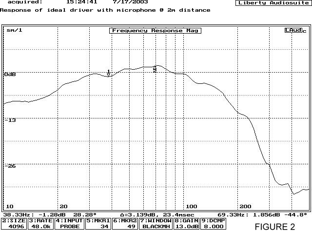 The actual room output is indicated in fig 2. The
acoustic energy seen in fig. 2 represents a flat
power response in the room (150 Hz high-pass filter engaged). Microphones
are located at 2 meters distance with the average response plotted
from various points about this distance. The small diameter driver
is acoustically loaded even into the infrasonic range therefore
requiring no subsonic filtering in most instances. Good response
is seen even down to 10 Hz. The room provides lift for very low
frequencies if they are present because of pressure from wall, ceiling
and floor reflections. Infrasonic frequencies won't cancel in small
rooms because they never complete their cycle before traversing
the room so they build pressure. This can be seen as the small lift
seen in fig. 1 at 15Hz is acoustically enhanced to the room lift
in fig.2. Some rooms are more efficient at loading low frequencies
with dimensions and cubic volume being major contributors.
The actual room output is indicated in fig 2. The
acoustic energy seen in fig. 2 represents a flat
power response in the room (150 Hz high-pass filter engaged). Microphones
are located at 2 meters distance with the average response plotted
from various points about this distance. The small diameter driver
is acoustically loaded even into the infrasonic range therefore
requiring no subsonic filtering in most instances. Good response
is seen even down to 10 Hz. The room provides lift for very low
frequencies if they are present because of pressure from wall, ceiling
and floor reflections. Infrasonic frequencies won't cancel in small
rooms because they never complete their cycle before traversing
the room so they build pressure. This can be seen as the small lift
seen in fig. 1 at 15Hz is acoustically enhanced to the room lift
in fig.2. Some rooms are more efficient at loading low frequencies
with dimensions and cubic volume being major contributors.
We haven't talked much about SPL as we must really provide a new reference for efficiency in the musical bass category. The TBI ETL/Reflex alignment represents the only manner of obtaining low frequency output in this manner therefore it is 100% more efficient than any contender. The output of the the Anti-Subwoofer is spread more evenly throughout the room and beyond.
This even diffusion of energy can easily surpass 100db peaks in a bass efficient room with a single bass module and not be so listener location dependent as most bass augmentation devices would have. This Thorough treatment of the bass spectrum however results in more enjoyment without excessive volume peaks in some areas.
Mass is necessary but static mass as required for any conventional low frequency system becomes a detriment to speed. Acceleration and decay characteristics must reflect a relatively small low mass cone, while good low frequency response requires a large high mass cone, an ongoing paradox in audio until now. The impedance graph fig. 3 shown below is like no other. Normally the peak on the left side of the graph is that of the port in a reflex system. This rise in impedance generally denotes a loss of loading with distortion and loss of output as the frequency goes lower. For those of you who are familiar with impedance plots you will notice the peak occurs at the same point in frequency as the maximum output of the driver or TL feedback peak 35Hz (see fig. 1). The TL feedback provides acoustic mass energy when the driver is unloading from its reflex alignment providing maximum output when the impedance is high. The phase response vs. impedance characteristic makes the system an easy load for any amplifier.
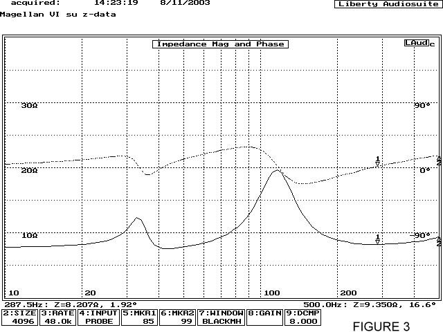 This frequency synthesized mass is not present at the higher bass
frequencies so as not to impede speed. This provides for an easy
load for the amplifier and eliminates the requirement for large
amounts of current to flow through the coil when the signal demands
are greatest. Heat build up during heavy bass passages cause distortion
and can cause physical damage. Fig. 4 below give
an indication of distortion with 5 w input at a frequency of 25Hz.
You must remember that this is a distortion figure for a 6"
low mass driver (<6g) operating in an enclosure of .25 cu ft.
This frequency synthesized mass is not present at the higher bass
frequencies so as not to impede speed. This provides for an easy
load for the amplifier and eliminates the requirement for large
amounts of current to flow through the coil when the signal demands
are greatest. Heat build up during heavy bass passages cause distortion
and can cause physical damage. Fig. 4 below give
an indication of distortion with 5 w input at a frequency of 25Hz.
You must remember that this is a distortion figure for a 6"
low mass driver (<6g) operating in an enclosure of .25 cu ft.
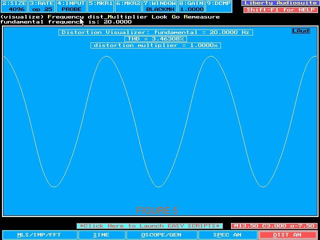
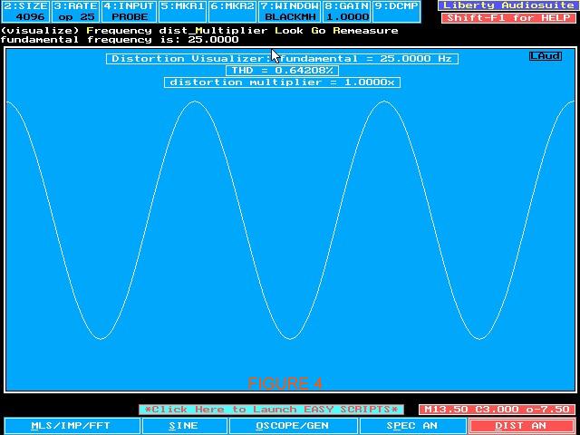 The distortion is controlled even during loud passages and with
loading to infrasonic frequencies the recorded ambiance is maintained
as part of the sonic event. The naturally synthesized mass improves
bass presence qualities at low volume levels. Distortion at 25 Hz
Fig 4 right and 20Hz fig. 5 below
represent graphs of the Magellan VI su. These frequencies are well
below port, driver or box resonance yet they exhibit a classic sine
wave. The TL feedback peak for the Magellan VIII occurs at 25Hz
with even lower extension and distortion.
The distortion is controlled even during loud passages and with
loading to infrasonic frequencies the recorded ambiance is maintained
as part of the sonic event. The naturally synthesized mass improves
bass presence qualities at low volume levels. Distortion at 25 Hz
Fig 4 right and 20Hz fig. 5 below
represent graphs of the Magellan VI su. These frequencies are well
below port, driver or box resonance yet they exhibit a classic sine
wave. The TL feedback peak for the Magellan VIII occurs at 25Hz
with even lower extension and distortion.